Bin frame — Bottom interface
Bottom interface
How-to guideThe component the chute rests on top of.
Parts needed
Bearings
- 1×
Printed parts
- 1×
- 1×
- 1×
- 3×
- 3×
- 1×
- 1×
Heat inserts
- 2×
- 8×
Screws
- 2× 8mm
- 8× 16mm
- 9× 16mm
Nuts
- 6×
A an interchangeable alternative works (hover for what).
Tools needed
- Hex keys, 2 mm for M3 and 2.5 mm for M4, plus 3 mm for an M5 button head or 4 mm for a socket head
- Soldering iron or heat-set insert press
- Drill or electric screwdriver
The bottom interface is the Lazy Susan bearing assembly the chute rests and spins on, slung underneath the bottom layer's frame.
Build it on the bench whenever you like, but fit it last. It is the Lazy Susan the bottom of the chute stack sits on, so it goes on once the frame is standing and the chutes are in.
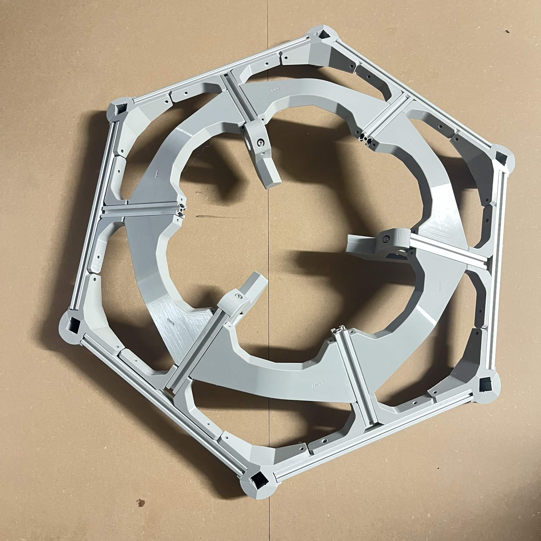
This assembly has no frame of its own. It hangs under the bottom layer's hex frame, built on bottom layer, so you don't need an extra one. Steps 5 to 10 work on that frame's spokes, from underneath.
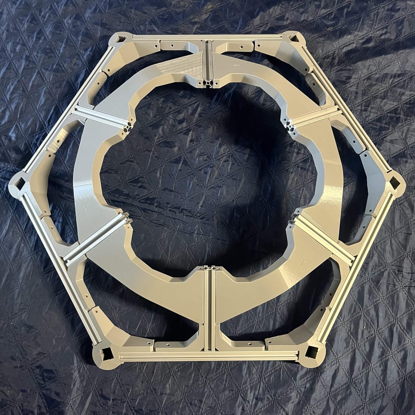
The parts list above is only the Lazy Susan bearing stack and the extrusion mounts added in steps 5 to 10, and its fasteners are called out inline at each step.
Fastener icons match the parts list: the silhouette is the head shape, the colour is the thread size. M3 M4 M5 M6
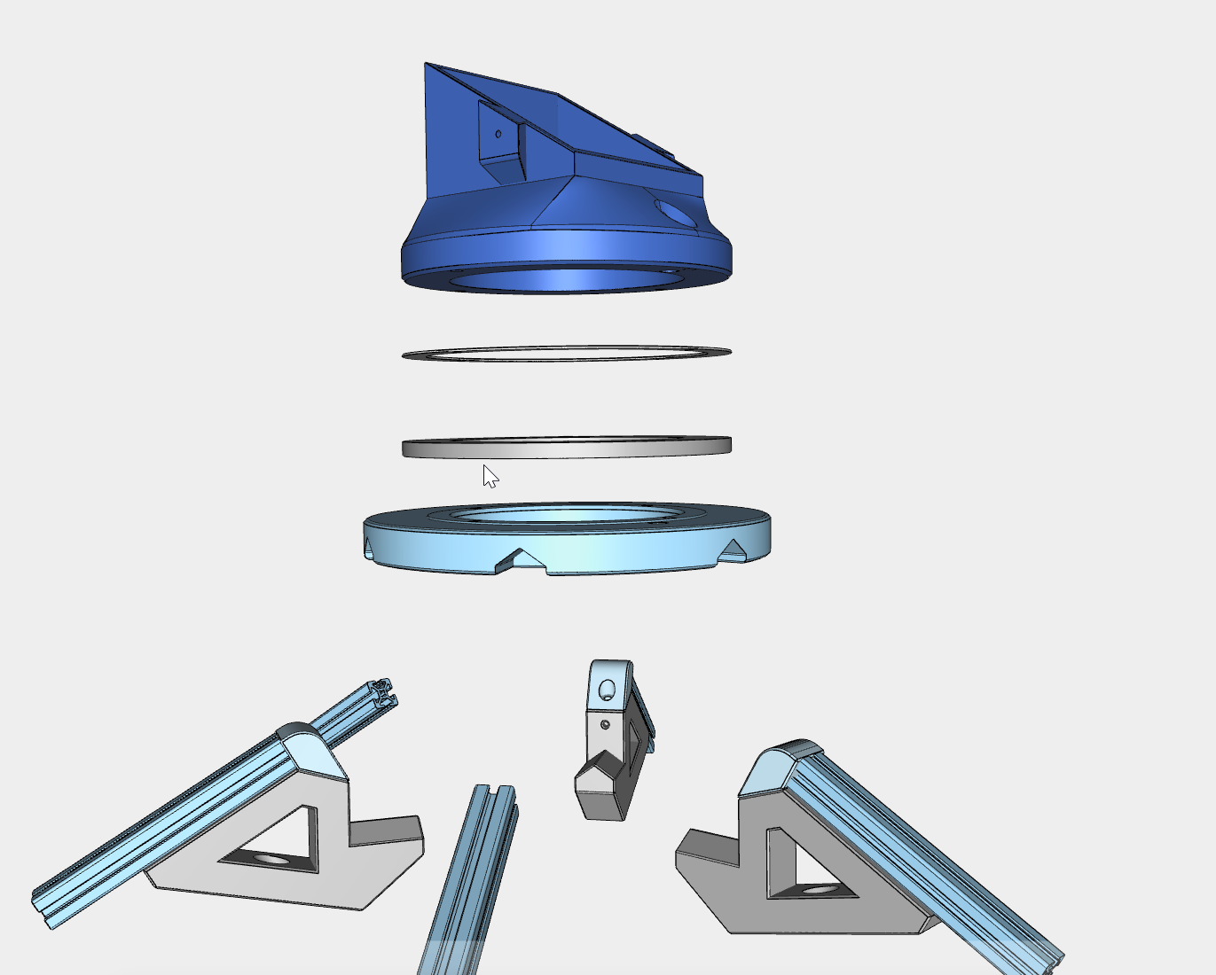
The bottom interface stacks the chute mount, the Lazy Susan washer, the Lazy Susan bearing, and the bottom static part. The Lazy Susan itself is two discs, inner and outer, that spin independently: the chute mount screws to one disc and the bottom static part to the other. Here it is exploded into its components:
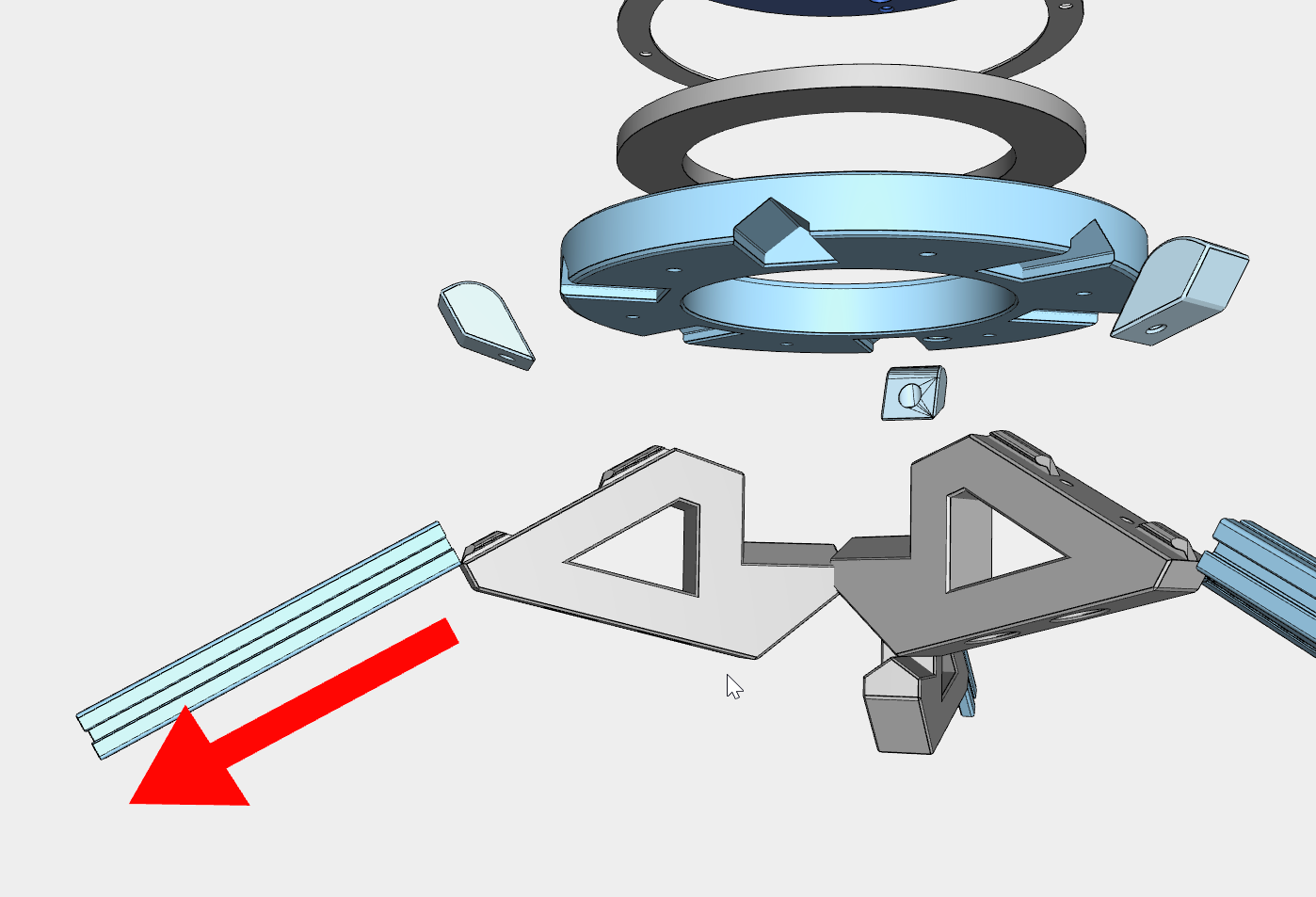
Once assembled, it mounts into the machine frame:
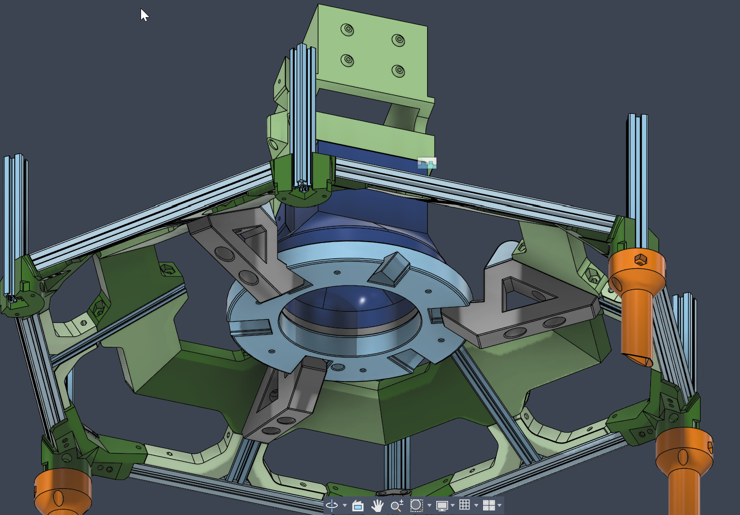
The corners in that render are out of date. It shows an ordinary bottom vertical and cover at floor level with the caster under it. On a build, each bottom corner takes the External bracket — foot cover, and the extrusion is piece D, running down through the corner to the foot connector the caster screws into. See bottom layer, steps 1 to 3. The Lazy Susan mounting in the middle of the render is right.
Step 1 Preparation
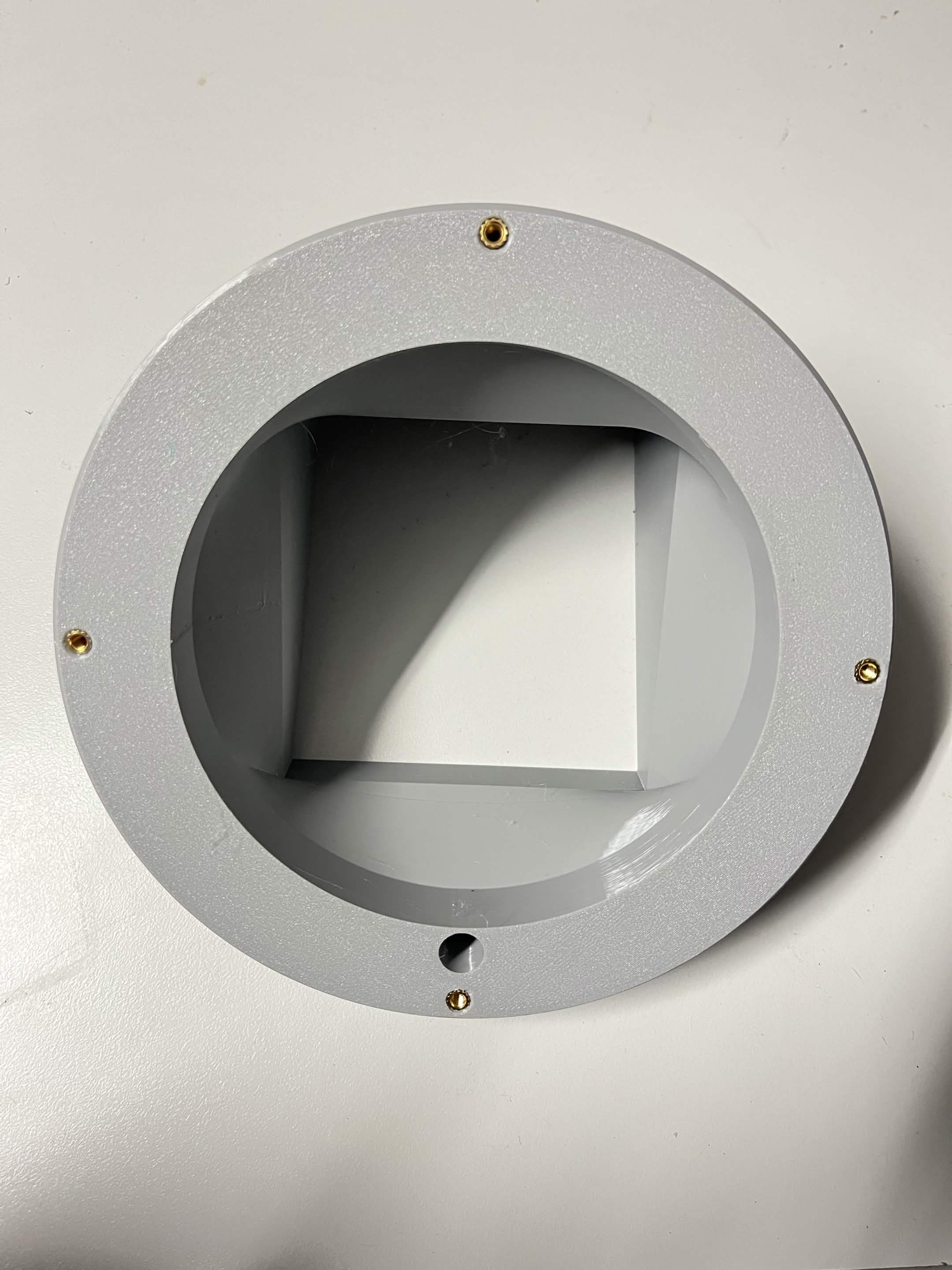
Press the heat inserts into both printed parts while they are still loose. See installing heat inserts for the technique.
Lazy Susan chute mount: 4 × M4, evenly spaced around the circular mounting face.
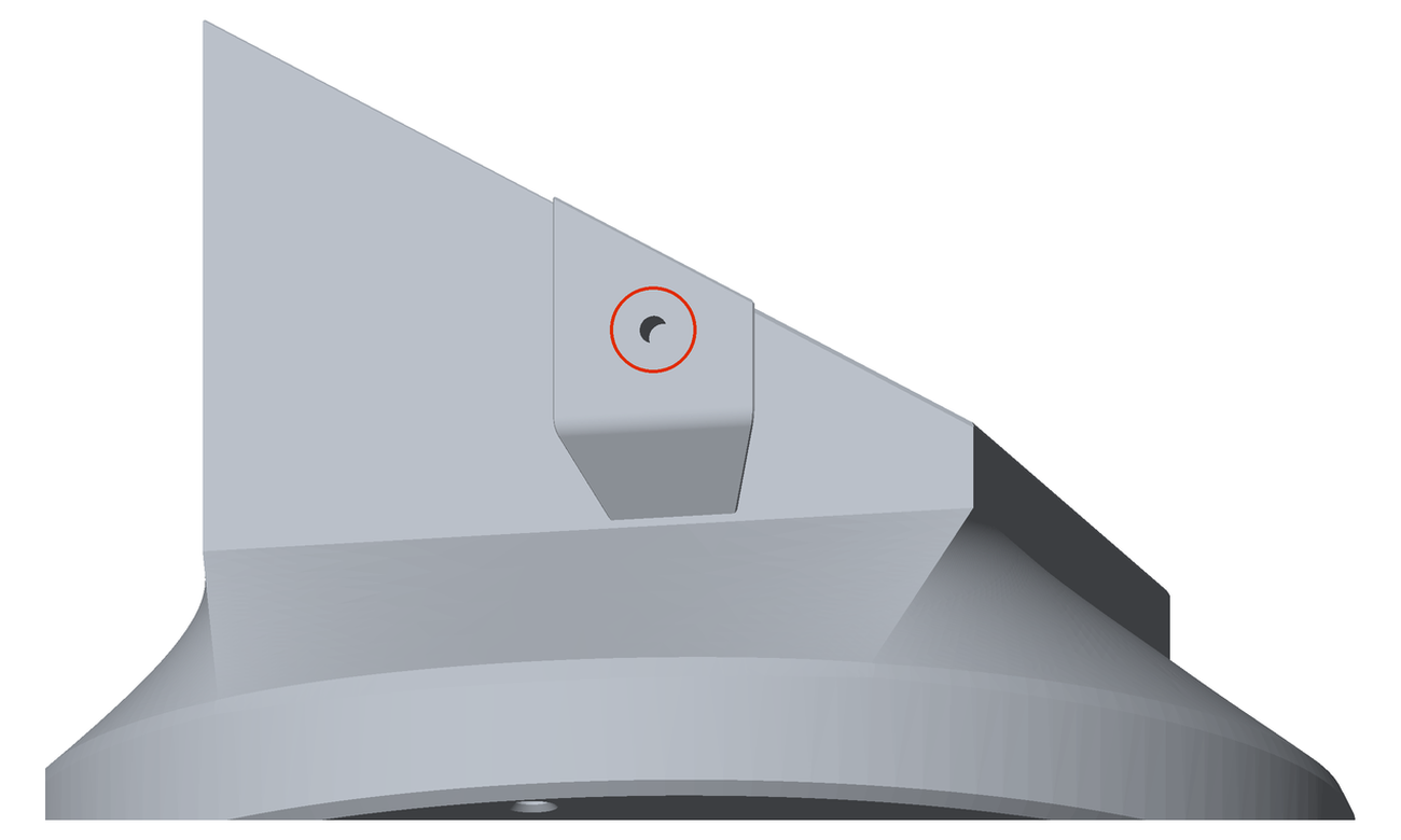
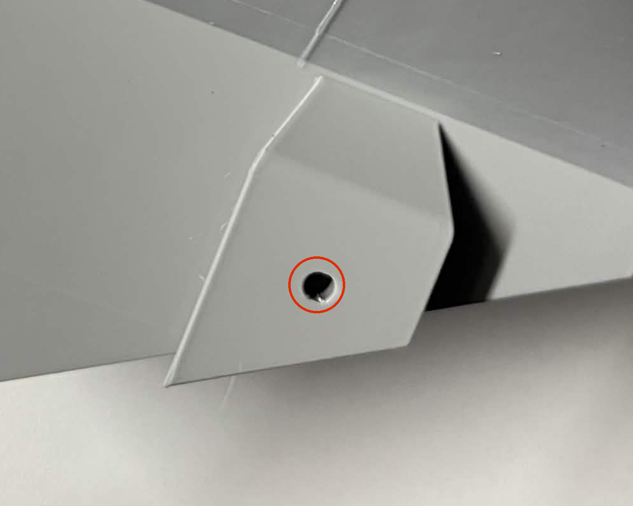
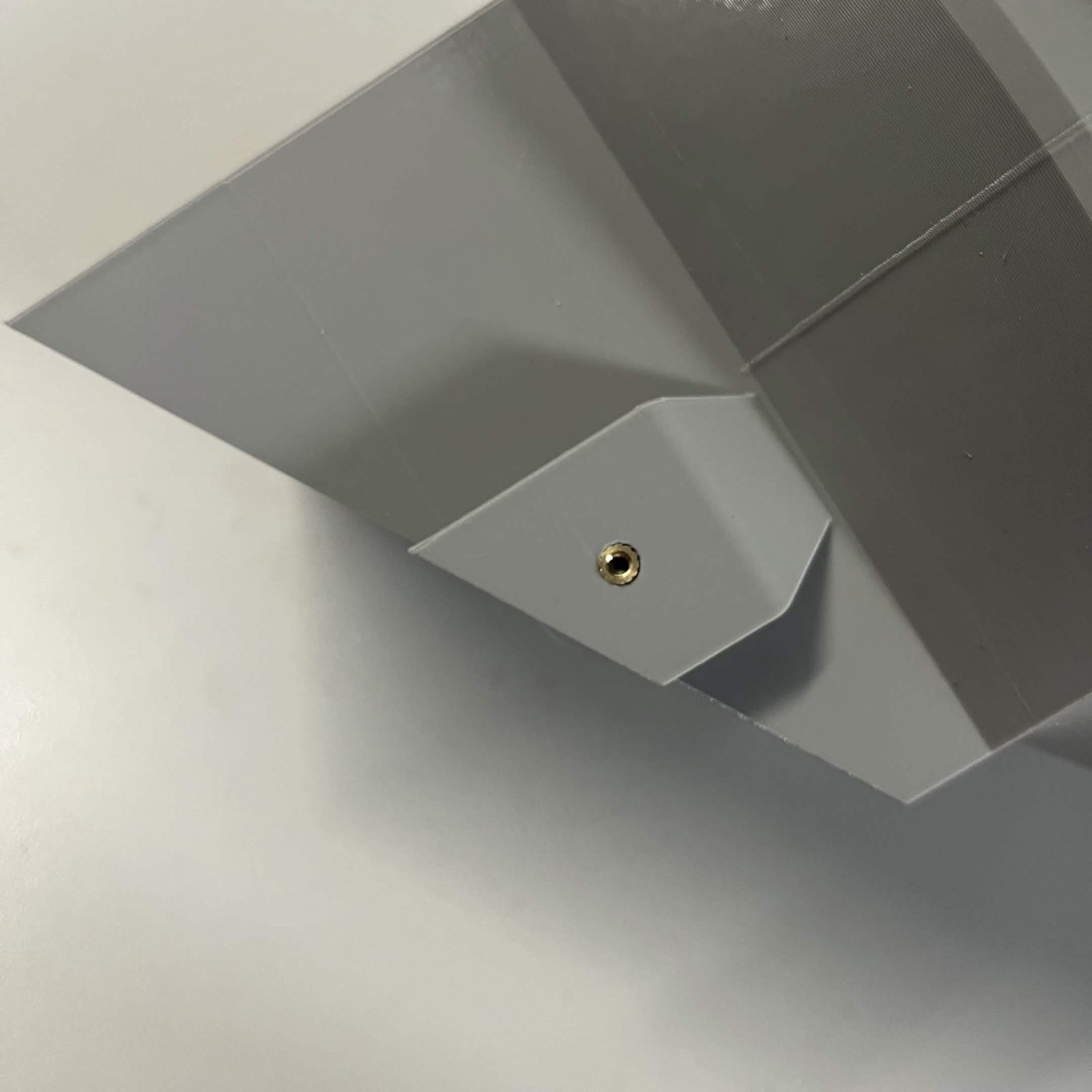
Lazy Susan chute mount: 2 × M3 for the layer connectors, one on each side face, on the small raised tab about halfway up.
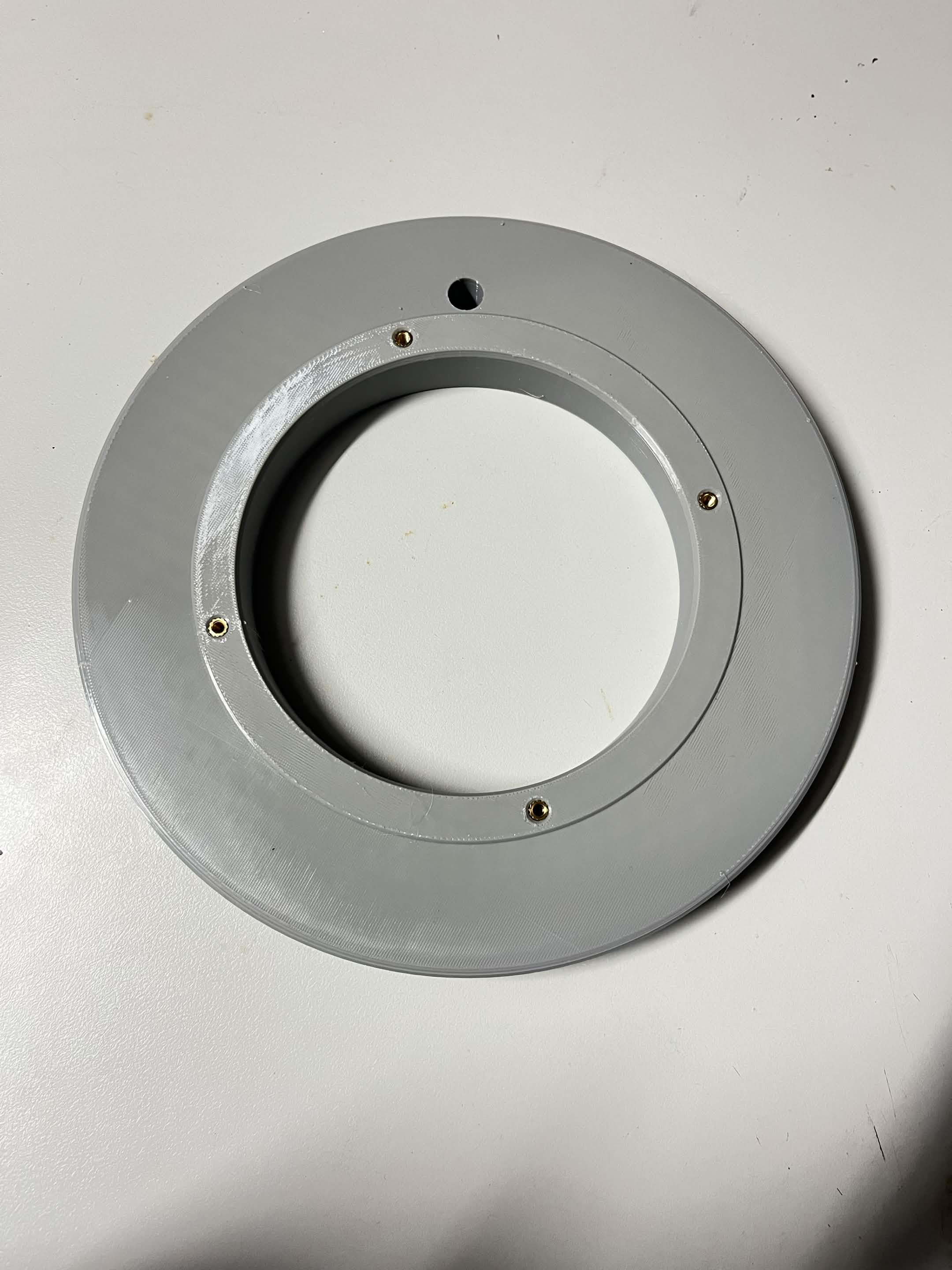
Lazy Susan bottom static: 4 × M4, evenly spaced around the top face.
Printed parts elsewhere in the machine take inserts too. Each assembly page lists its own in a Preparation step like this one.
Step 2 Mount the Lazy Susan to the chute mount
This step and the next work on opposite faces of the same bearing.
Remove the Lazy Susan's rubber tabs first (see Preparing Lazy Susan). The washer goes on before the bearing: set the Lazy Susan washer on the chute mount, then the Lazy Susan on top of that.
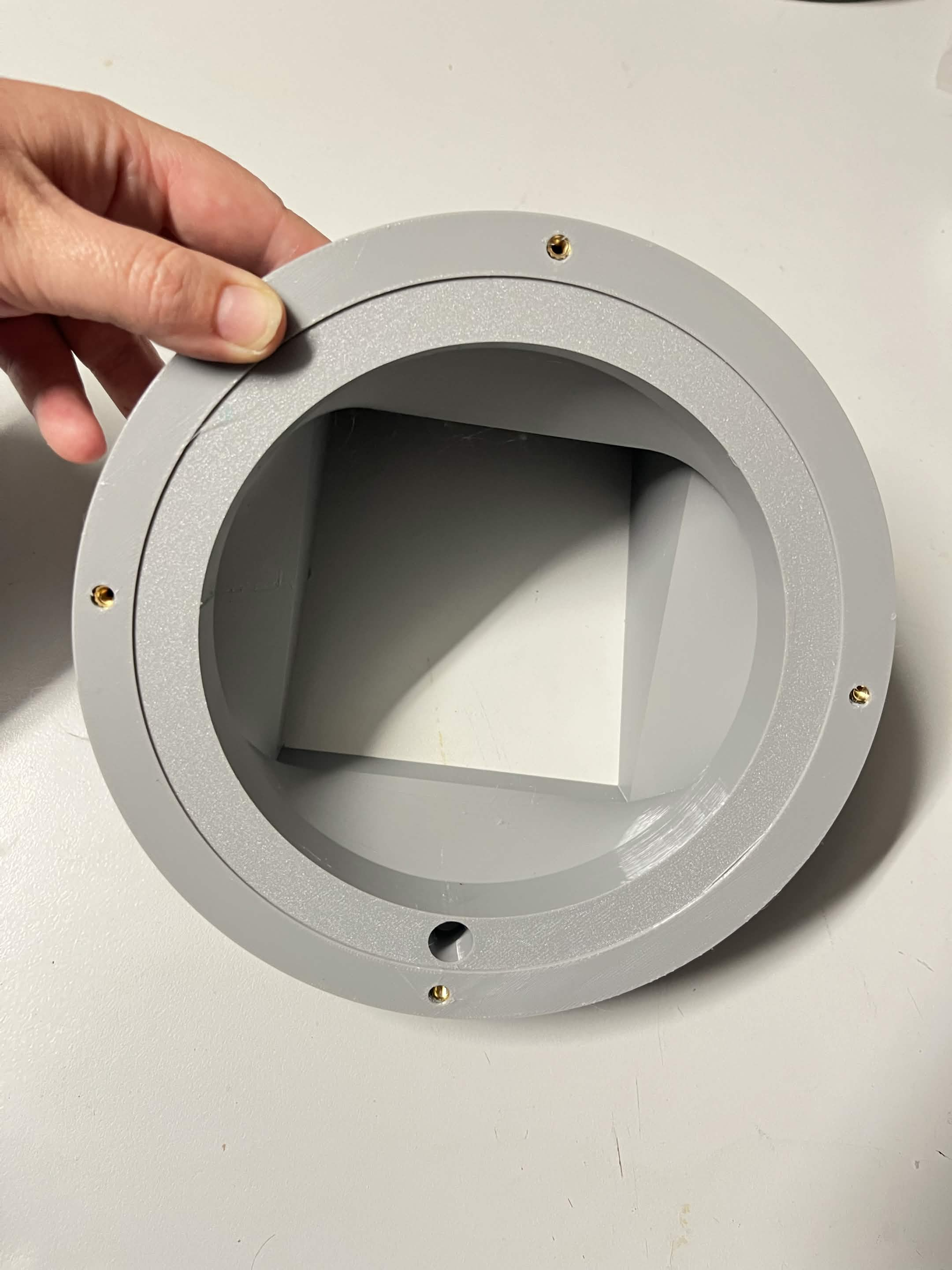
Line up a hole in the disc with one of the chute mount's inserts, drive an M4 × 16 mm countersunk screw, and repeat around the disc.
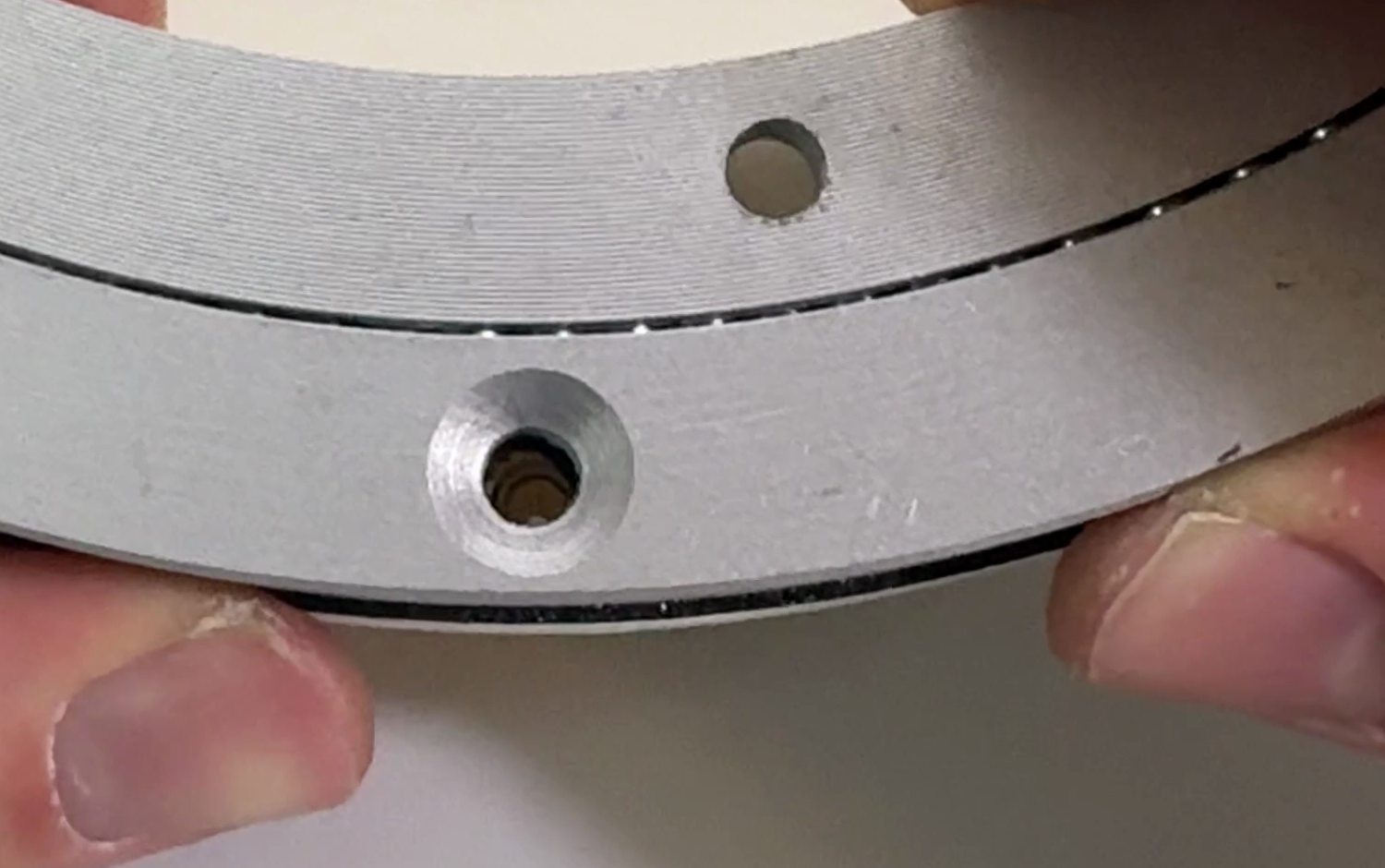
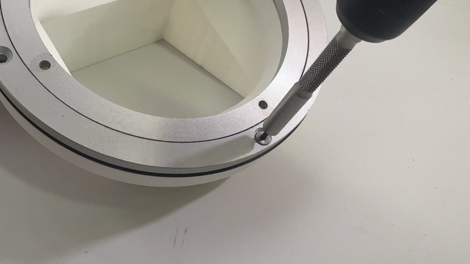
The M4 × 16 mm countersunk screws must be very tight. A drill or electric screwdriver will not get them there, so finish them with a hex key by hand. Machine vibration works a loose one out of a spot that is a hassle to reach later.
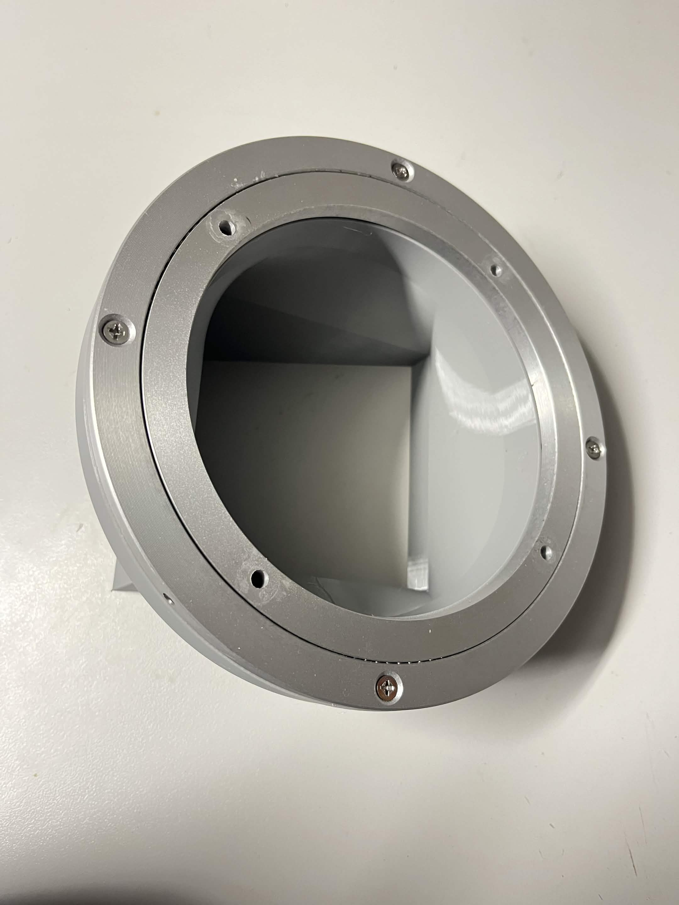
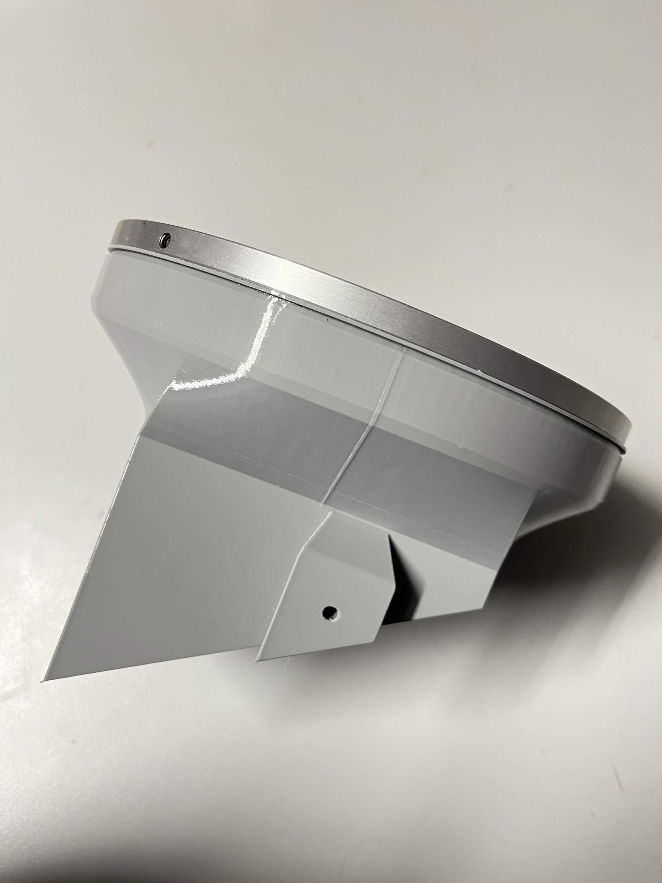
Step 3 Mount the Lazy Susan to the bottom static part
The bearing's other disc screws down into the bottom static part. All four of those screws go in through a single pass-through hole in the chute mount, rotating the assembly between each one.
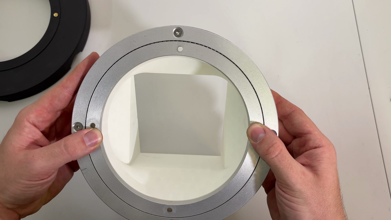
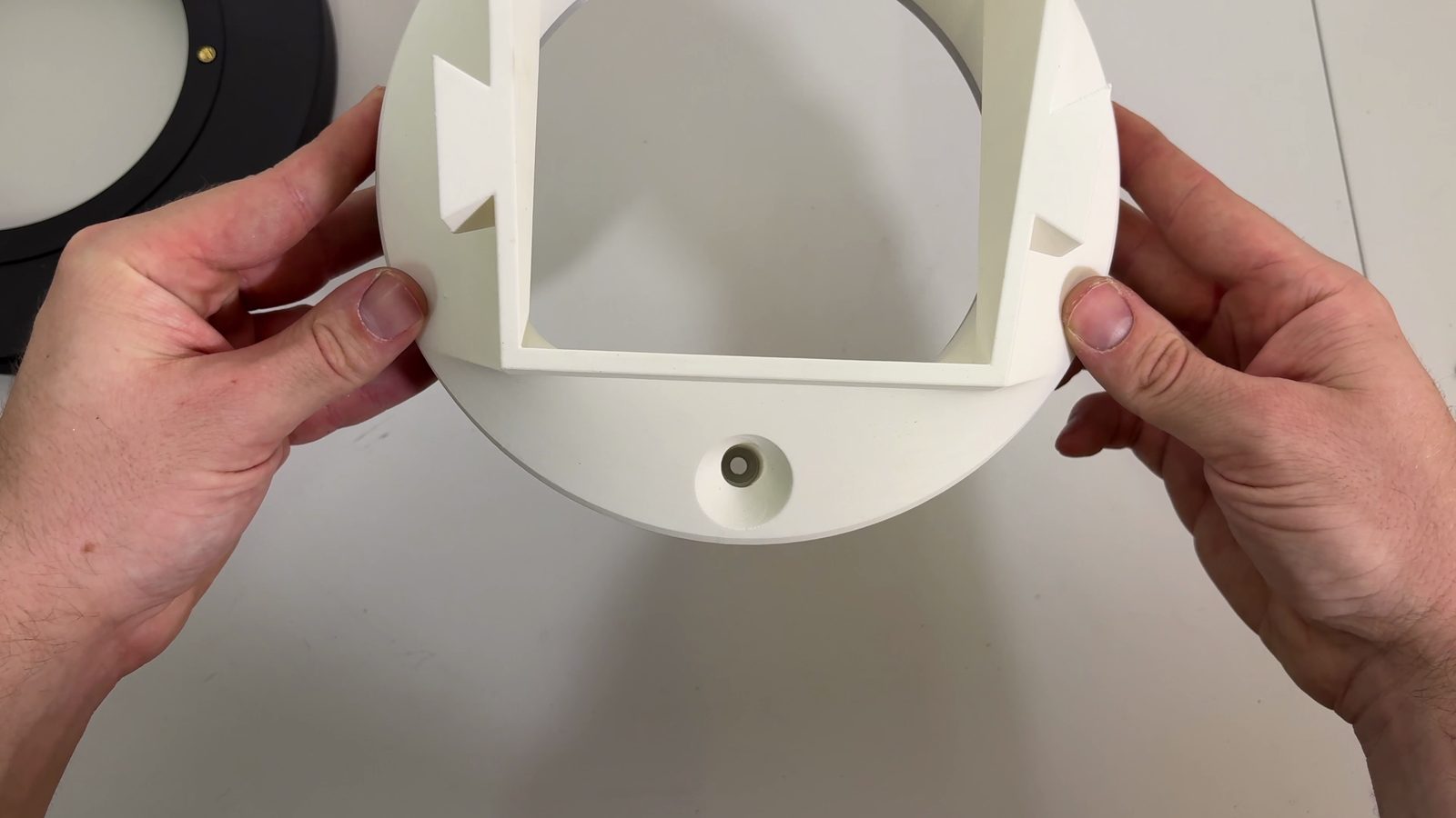
Set the chute mount and Lazy Susan assembly onto the bottom static part, then line up the pass-through hole with the insert marked by the red square.
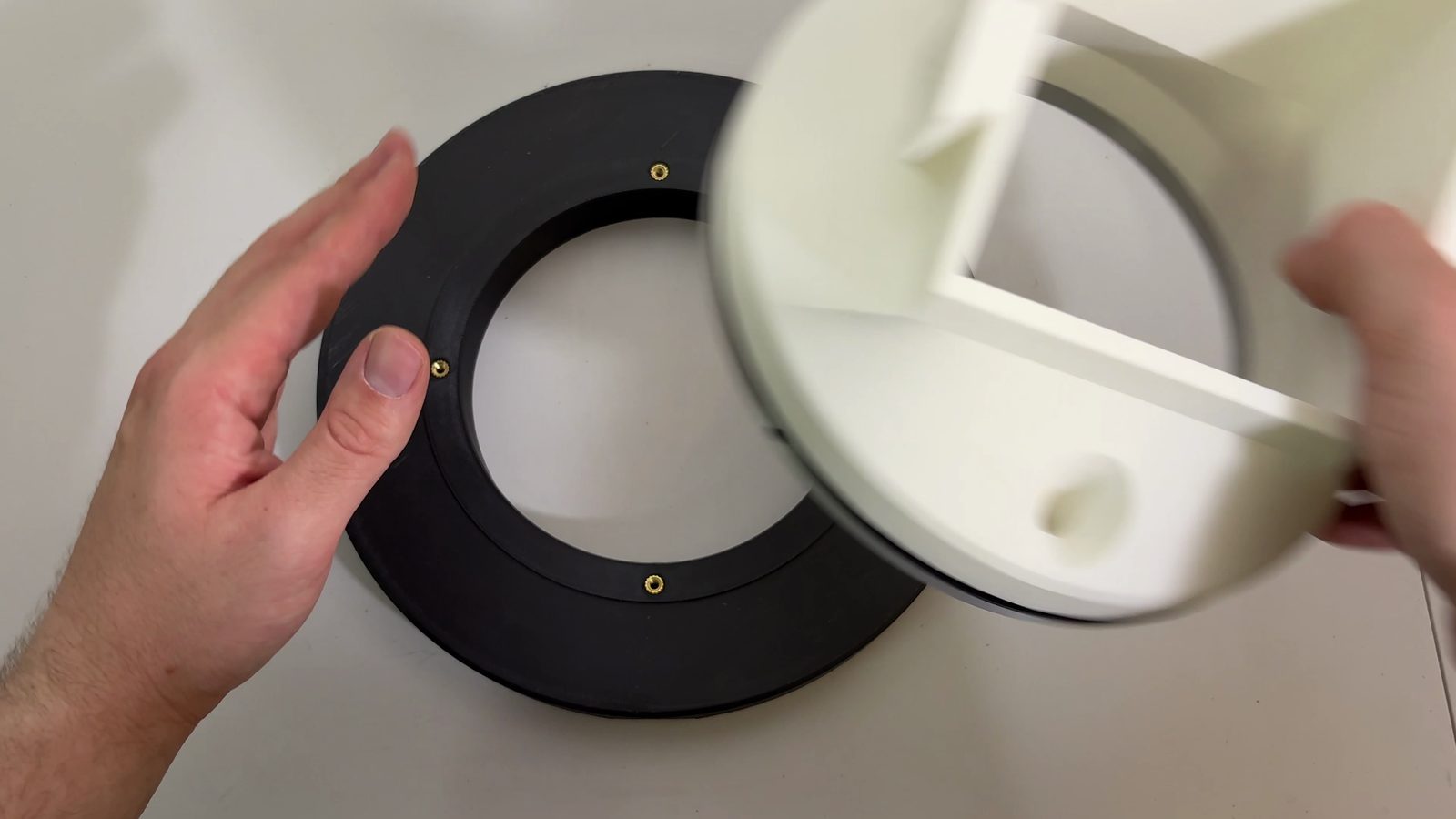
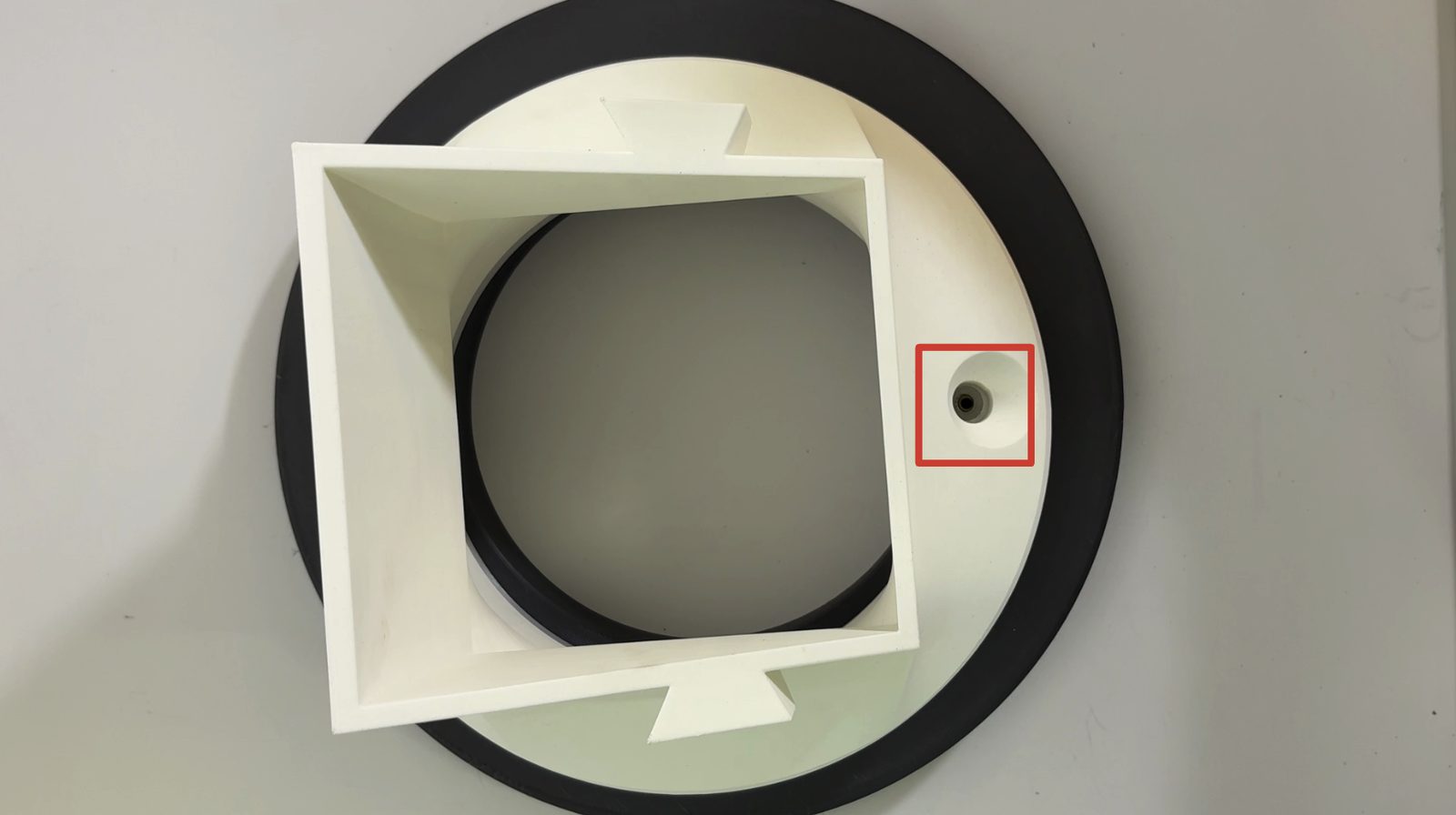
Drive the first M4 × 16 mm countersunk screw through the pass-through hole. Don't tighten it fully yet, leave some play while you get the rest of the four seated.
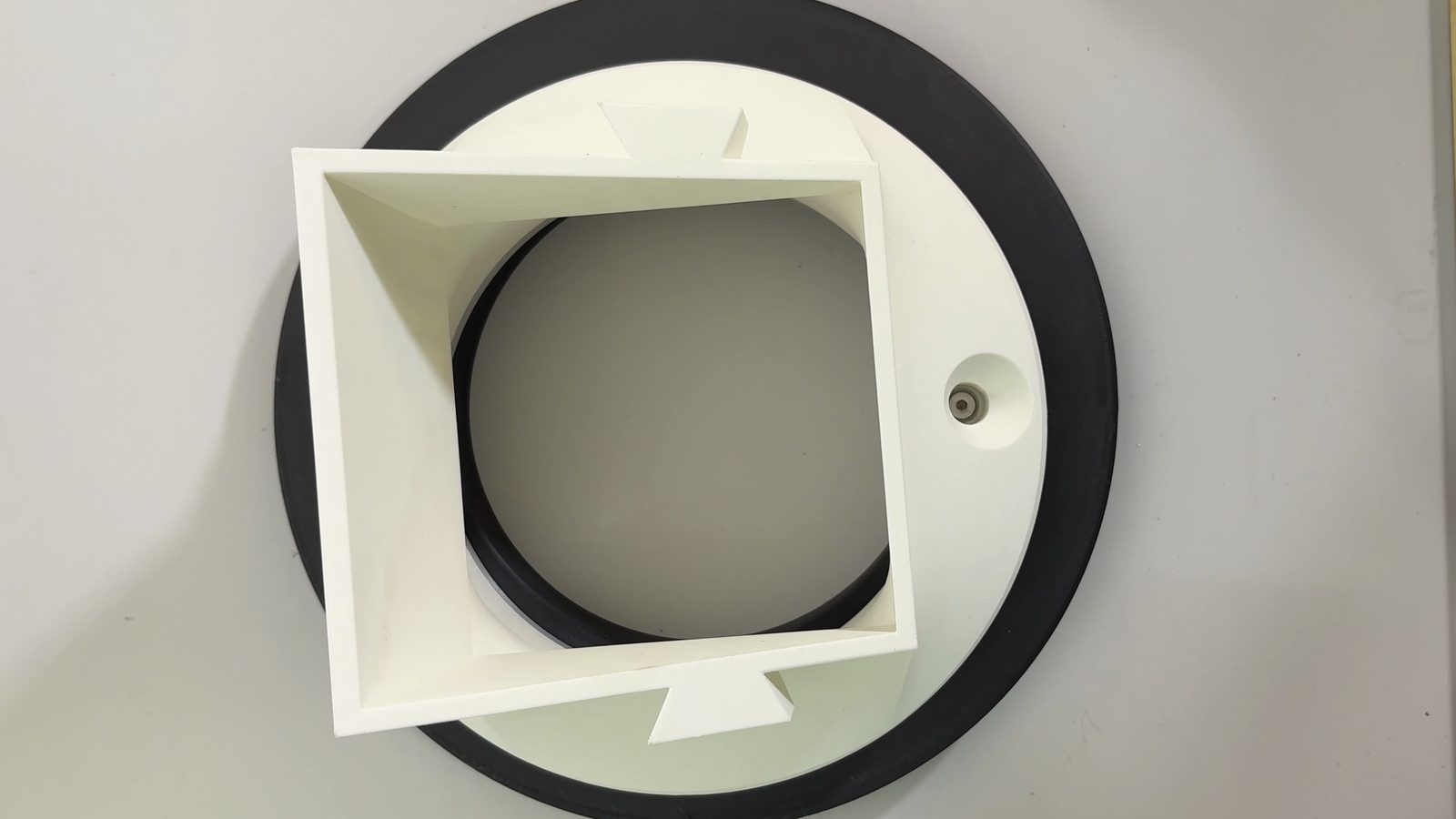
Rotate the chute on the Lazy Susan, the way it turns in normal operation rather than forcing the whole assembly, to bring the pass-through hole over the next insert. Repeat for all four screws, then tighten all four the rest of the way.
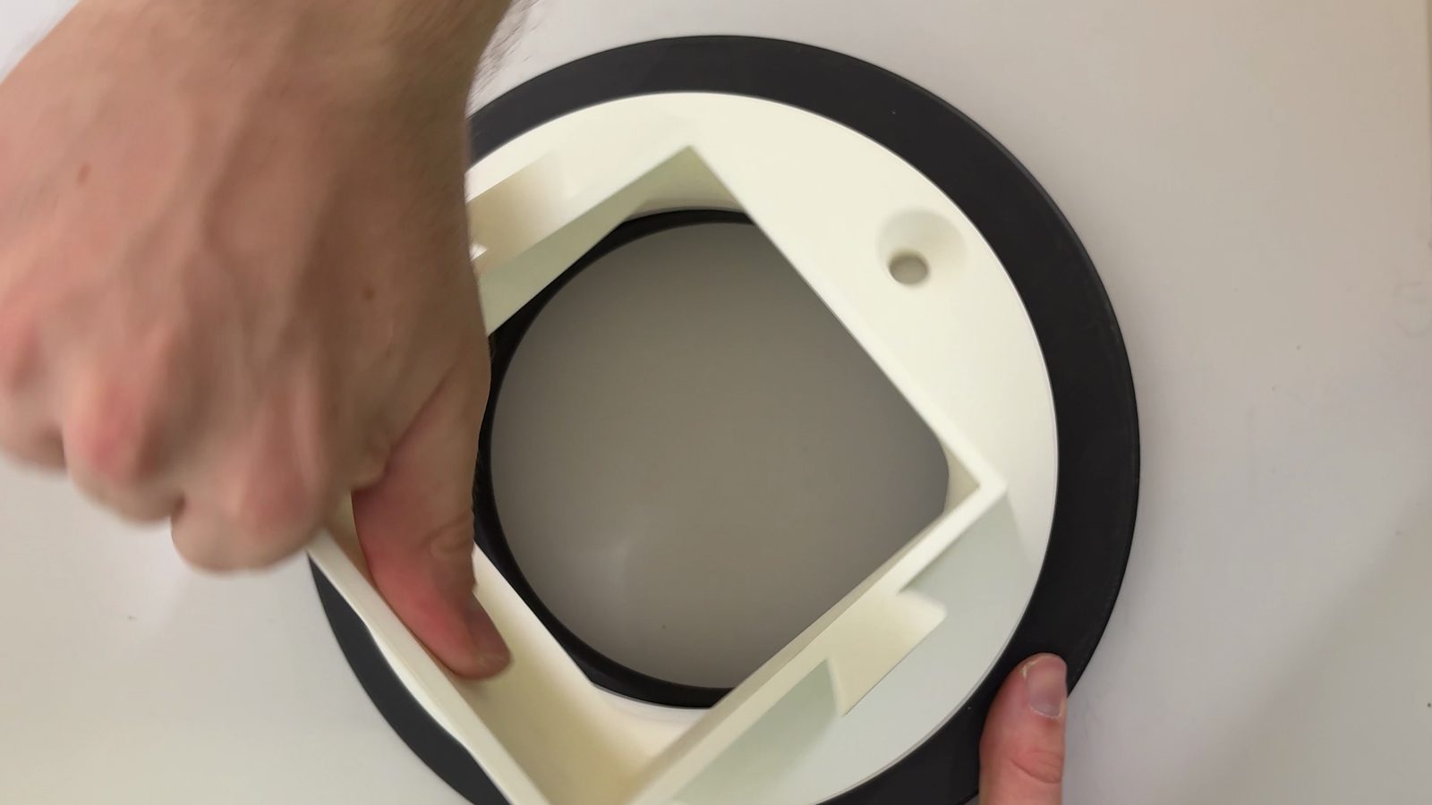
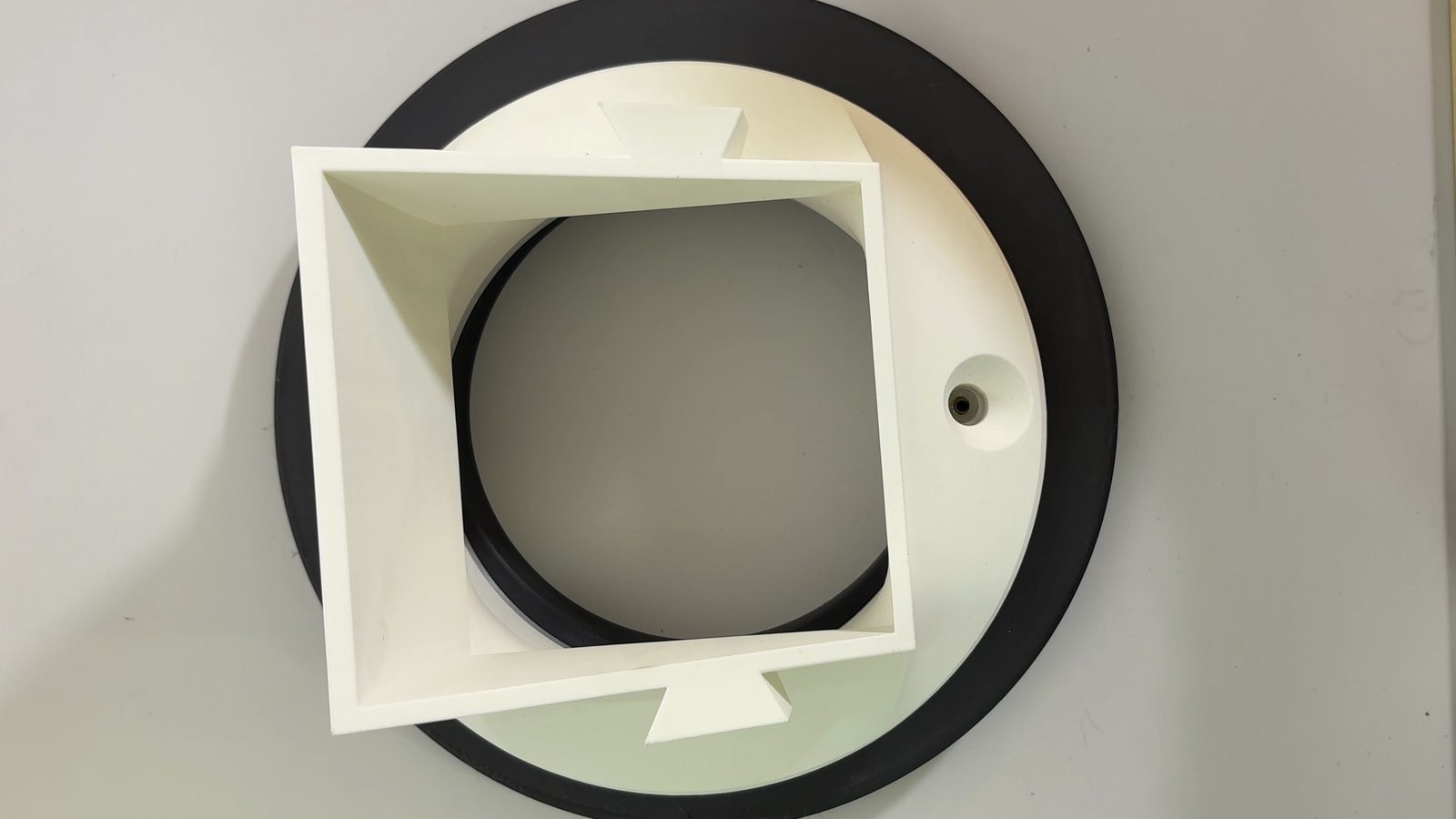
The bearing stack is now complete:
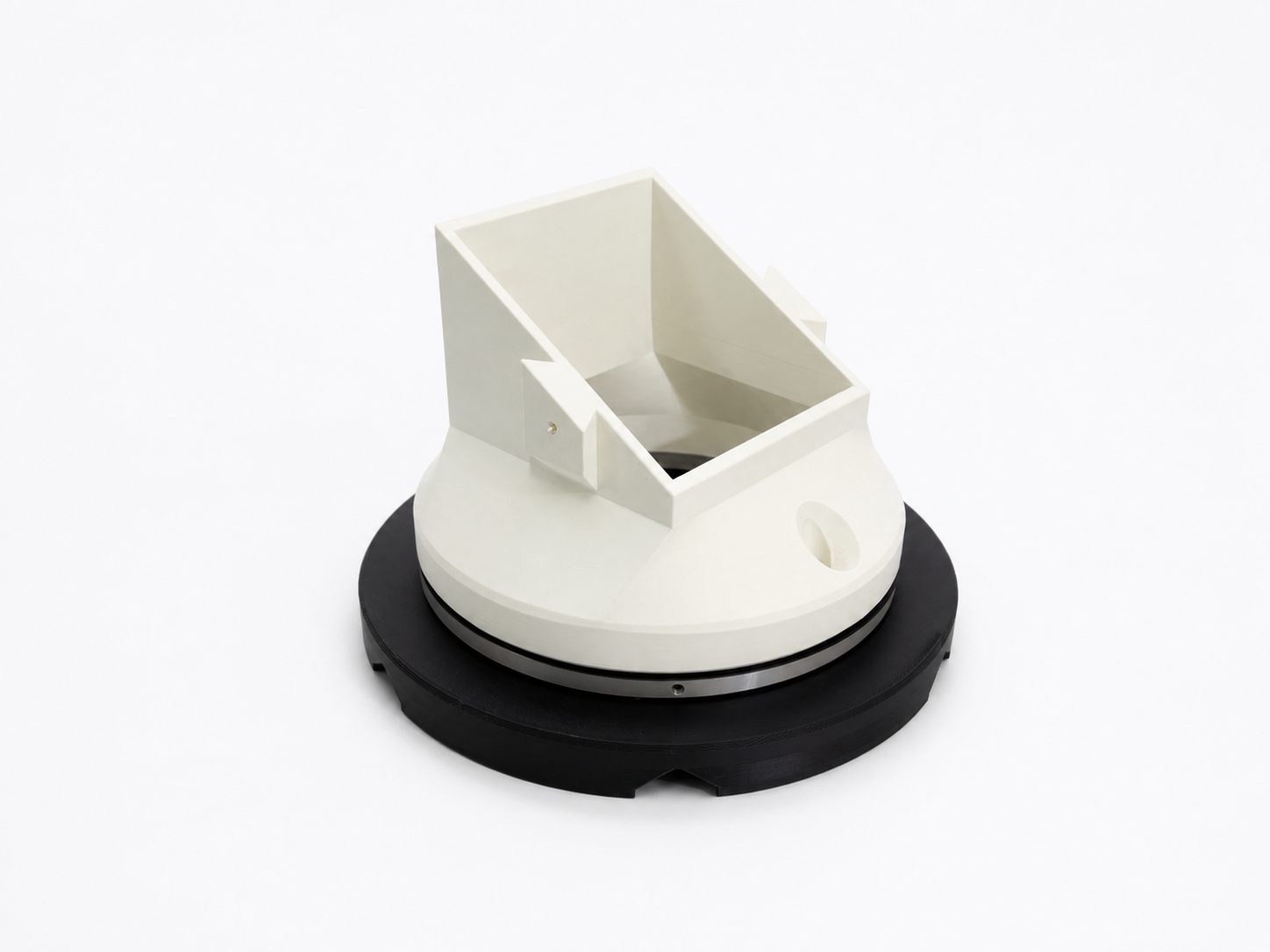
Step 4 Add the two layer connectors
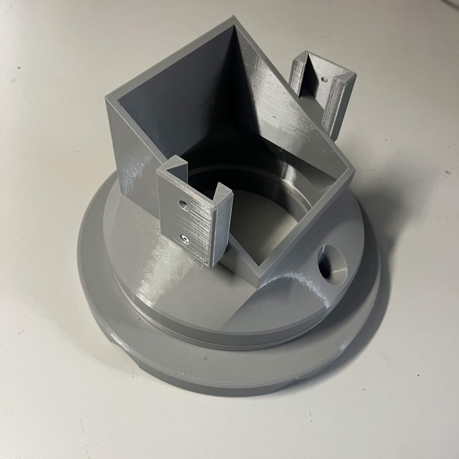
A Layer connector A and a Layer connector B go onto the chute mount, one on each side face, into the two M3 inserts pressed in step 1. One M3 × 8 mm countersunk each. They are the same pair that joins every chute to the one above it; here they are what the bottommost chute lands on.
With them on, the bearing stack is complete: chute mount, Lazy Susan, washer and bottom static, plus the connectors that carry the layer above.
Step 5 Bolt a hold in place to each mount
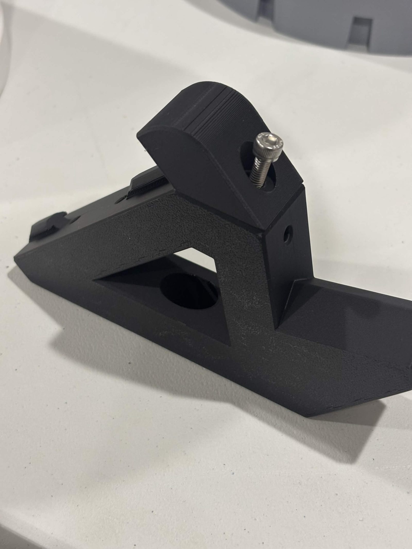
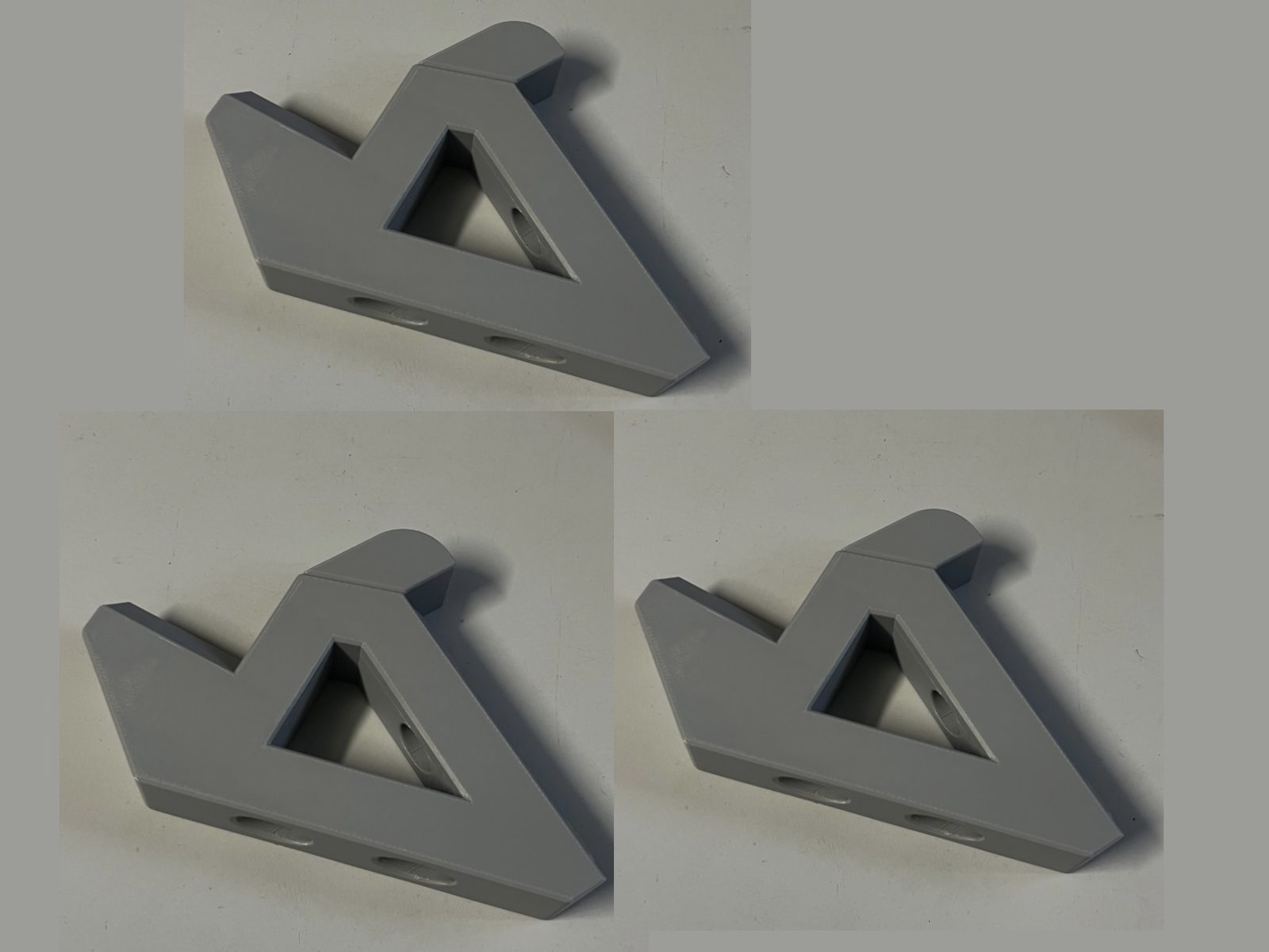
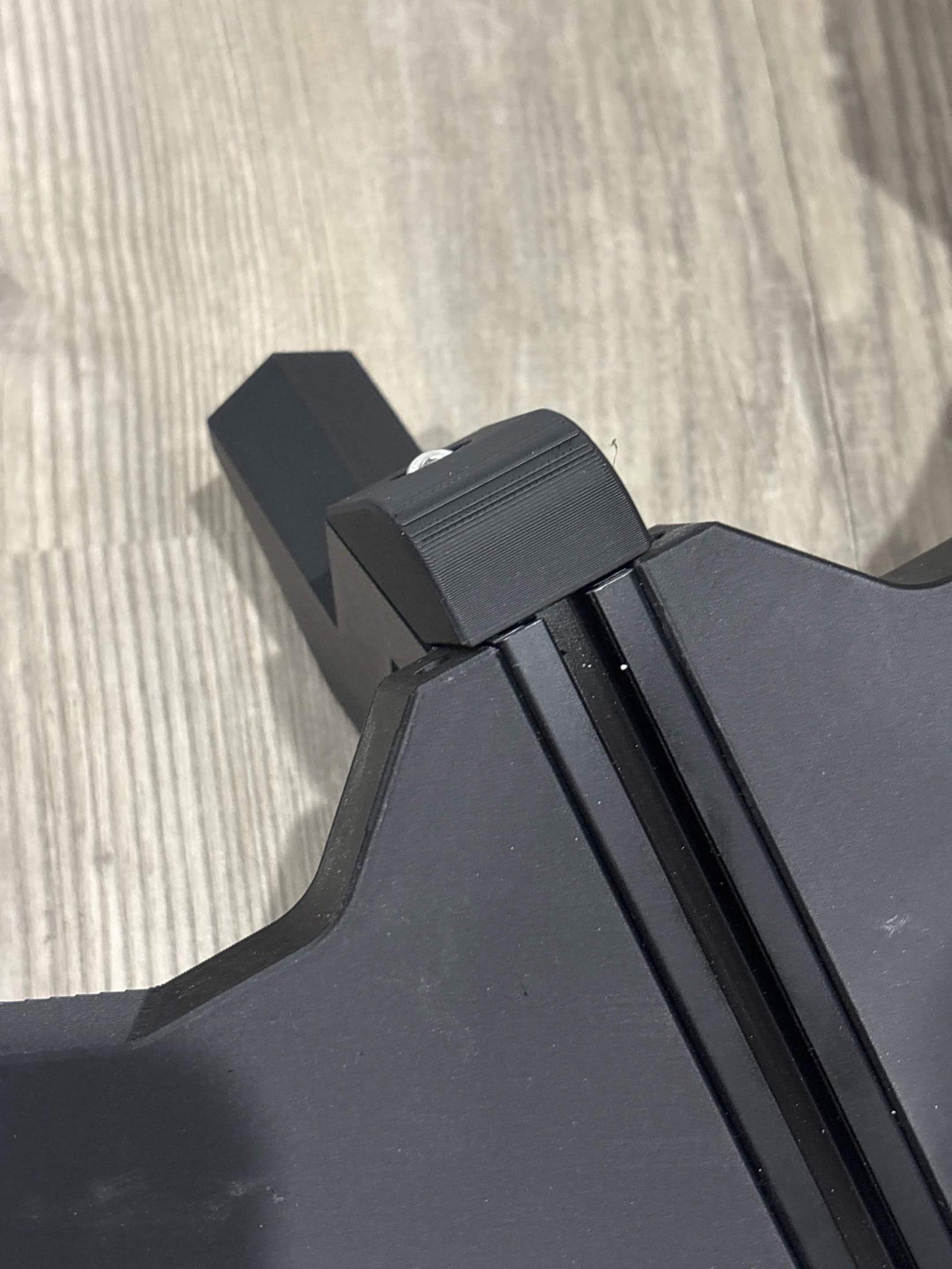
Bolt a hold in place onto each mount with one M5 × 16 mm socket / button head , before either part touches the extrusion.
Step 6 Prestart the T-nuts
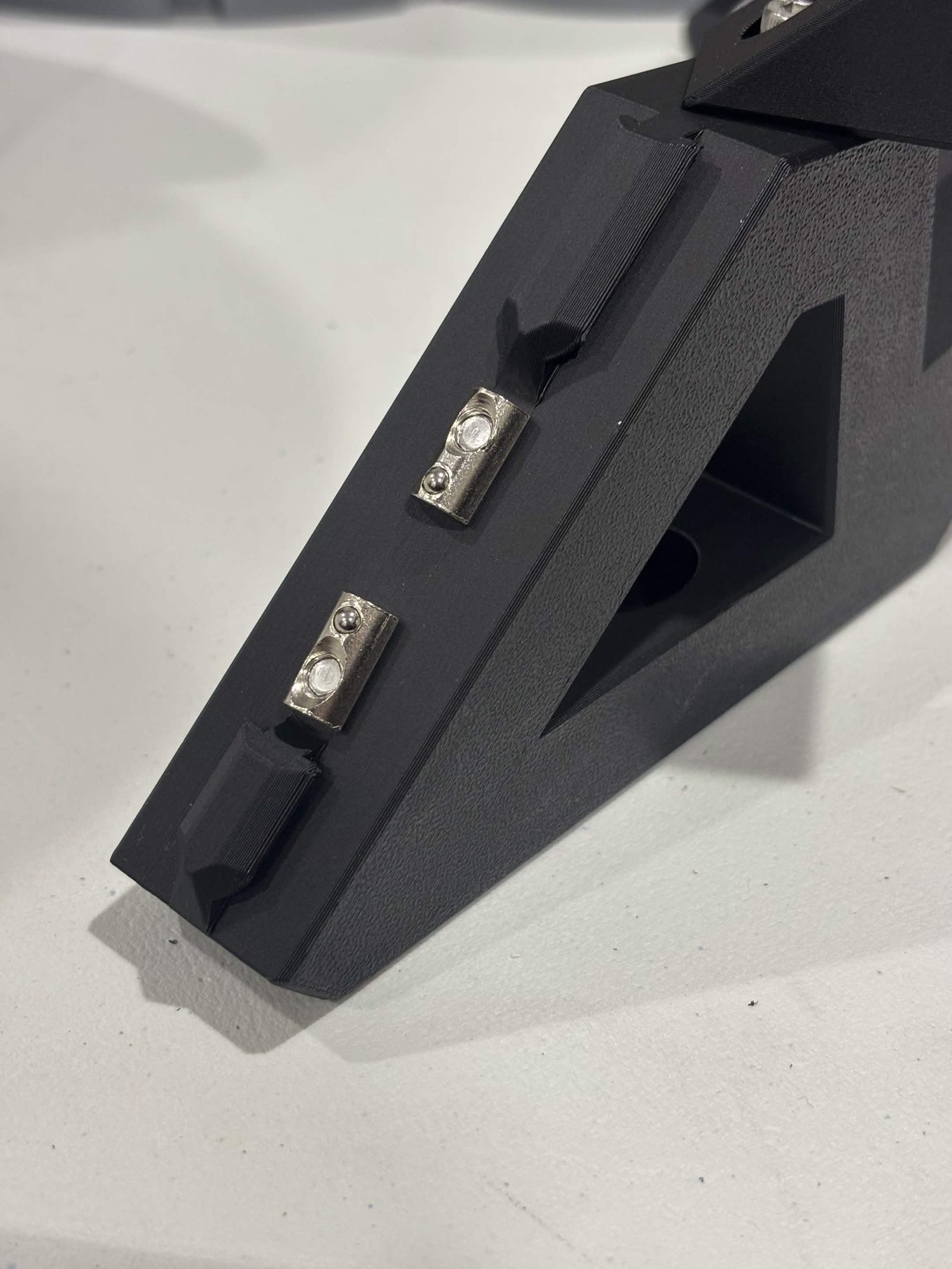
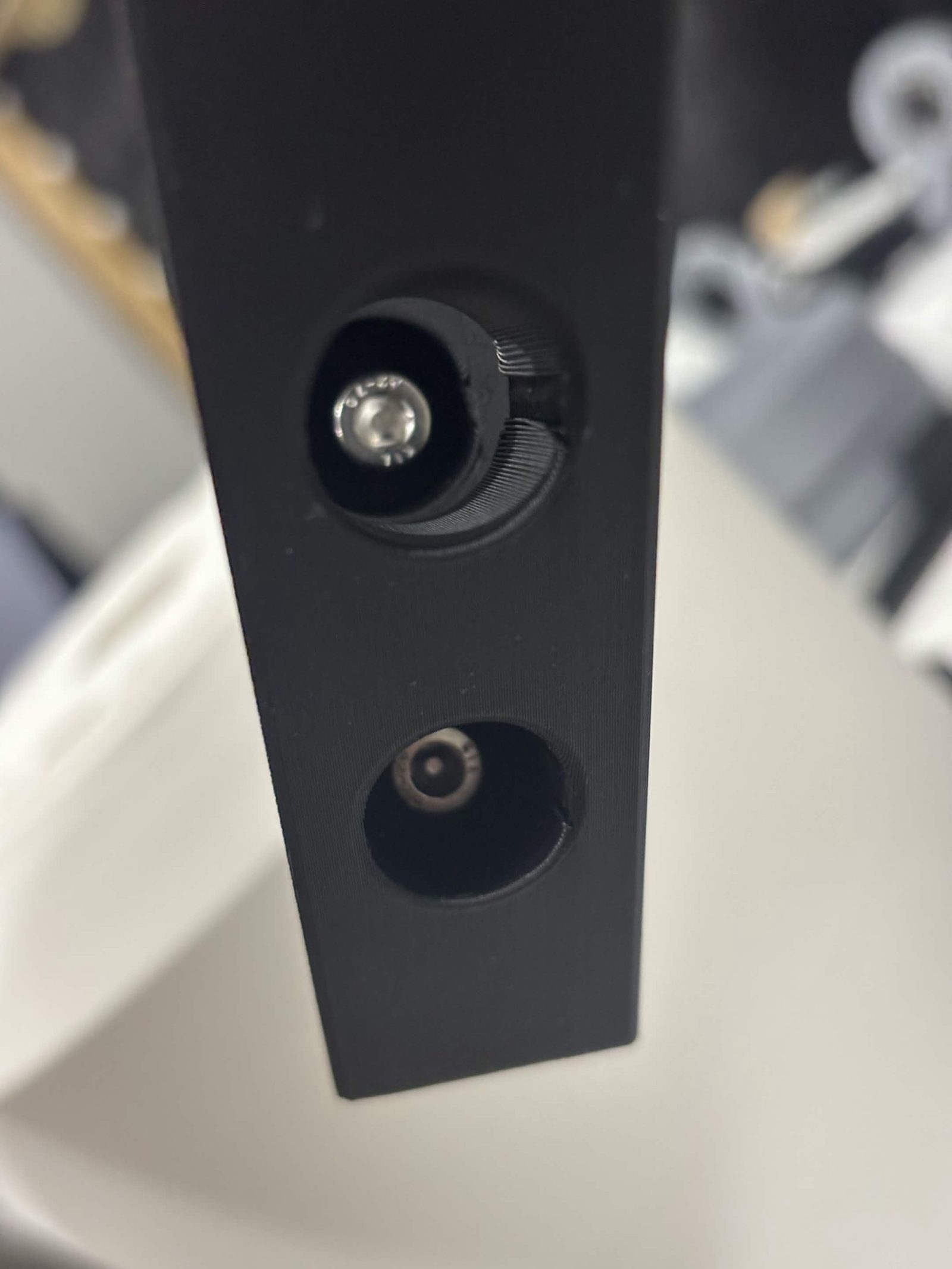
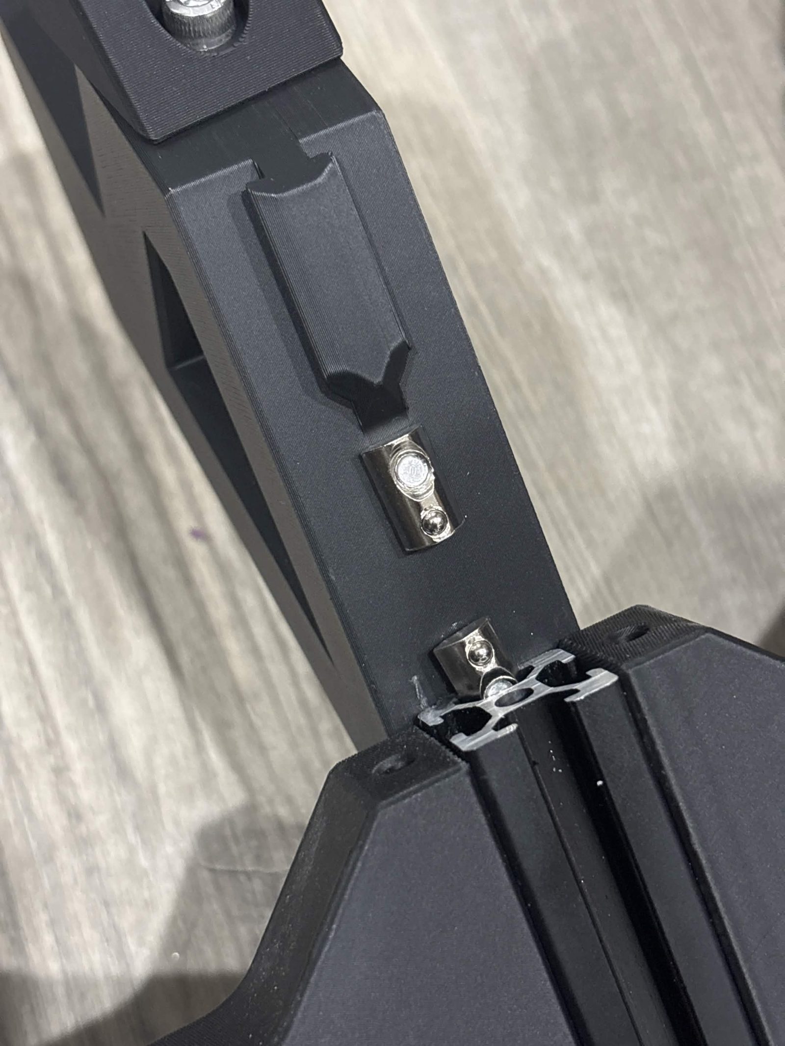
Drop an M5 × 16 mm socket / button head through each of the mount's two counterbored holes and start a M5 T-nut on the end, two or three turns. Leave them loose enough to swing. See Fitting T-nuts for how they go in.
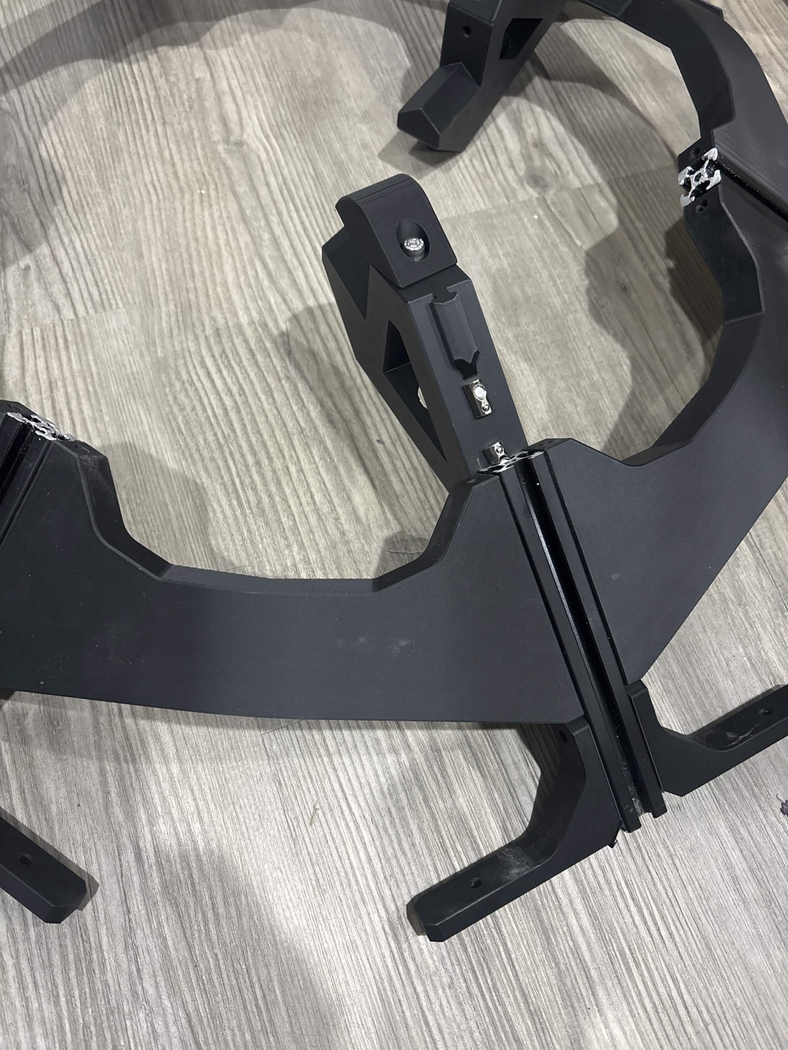
Step 7 Slide the mount onto the spoke
Slide the mount onto a B spoke (158 mm) already in the frame, T-nuts into the extrusion slot. Push up on each nut with a screwdriver as it goes, so it seats square.
Step 8 Tighten
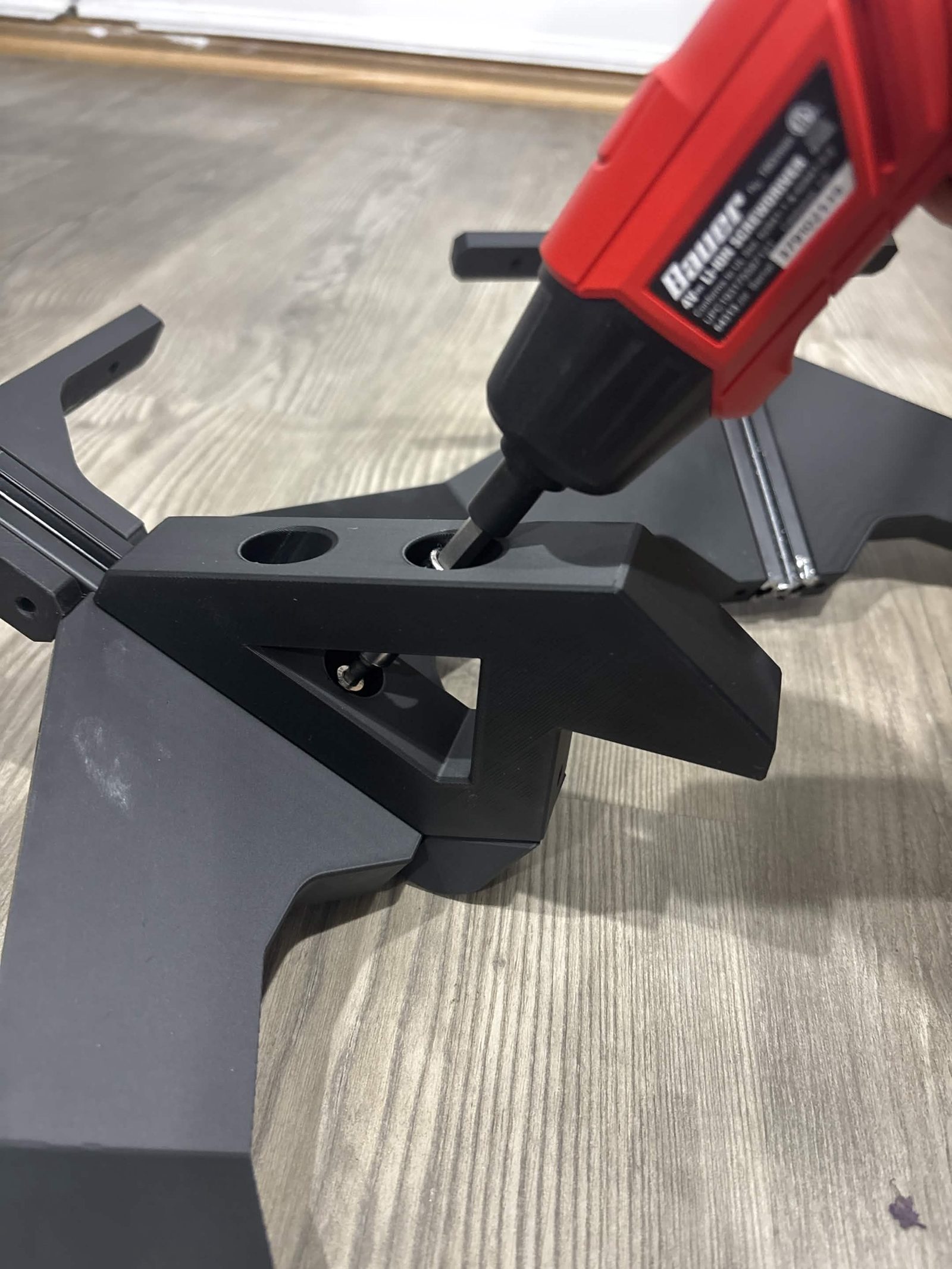
Tighten both M5 × 16 mm socket / button head screws into the T-nuts.
Step 9 Repeat for the other two mounts
Nine M5 × 16 mm socket / button head and six M5 T-nut across all three.
Step 10 Lower the bearing stack onto the mounts
Set the bearing stack from steps 1 to 4 down onto the three mounts, so the Lazy Susan bottom static part lands in the triangular cutouts.
Nothing screws it down. The cutouts hold it in position, and the weight of the chute stack that hangs from it afterwards keeps it seated.
The finished result
The bearing stack sitting in the three mounts, ready for the chute core. With a funnel fitted, it lands level with the bin entrances.
The Bin frame page contains the instructions for the entire stack, and is where you should return once you're done here.