Distribution — External bracket
External bracket
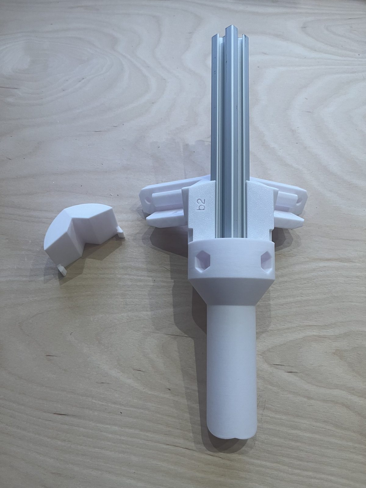
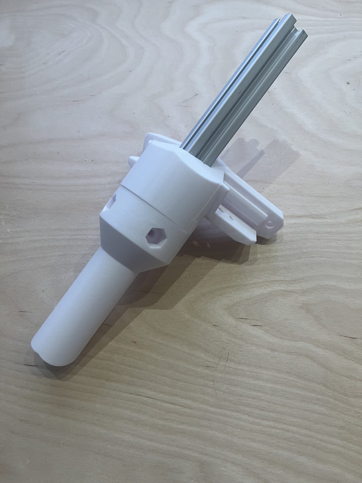
How-to guideThe bracket that mounts a distribution-frame vertical extrusion to the frame and gives it a mounting point.
Parts needed
Printed parts
Screws
- 4×M5 × 16 mm socket head cap screw
Three printed parts that bolt together into one external bracket. 6 per distribution frame (per layer), plus one set per interface.
| Part | Qty per bracket | Qty per machine (6 brackets/layer) | Weight | STL |
|---|---|---|---|---|
| External bracket — side | 1 | 6 | 48.5 g | Download STL |
| External bracket — bottom vertical | 1 | 6 | 50.6 g | Download STL |
| External bracket — cover | 1 | 6 | 12.4 g | Download STL |
Other parts
| Part | Qty per bracket | Notes |
|---|---|---|
| C-Layer vertical support (extrusion) | 1 | The vertical aluminum extrusion the bracket clamps onto. |
- No heat inserts are used on this assembly. Joining is self-tap: the M5 × 16 mm screws thread directly into the printed plastic.
- The most-used M5 in the machine, the same screw used on every external bracket, every bin bracket, every interface rib, and every lazy Susan extrusion mount.
- Of the four M5 × 16 mm screws: 2 join the bottom-vertical part to the side bracket, and 2 clamp the side bracket against the C-Layer vertical support to hold it in place. The cover clips on, it takes no screws.
- Matching parts from the same print run are embossed with a shared set code (e.g. "b2") on both the side bracket and the bottom-vertical part, keep marked pairs together so brackets don't get mixed across sets.
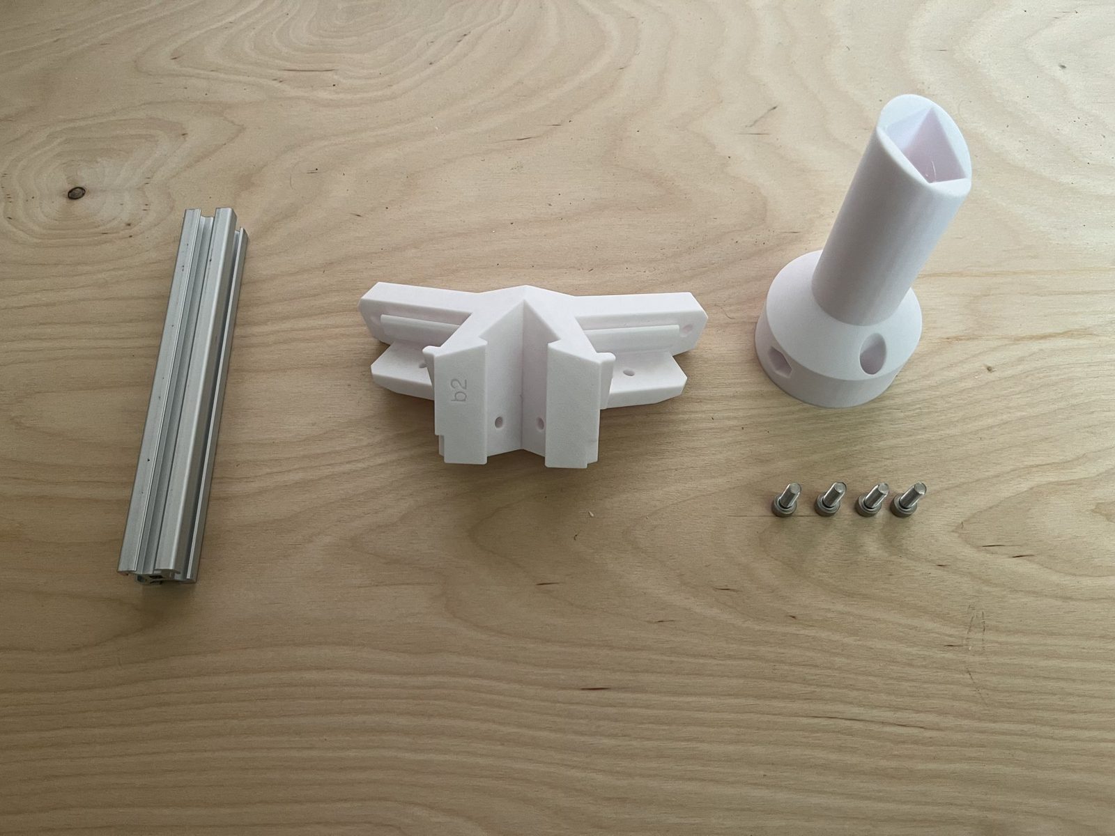
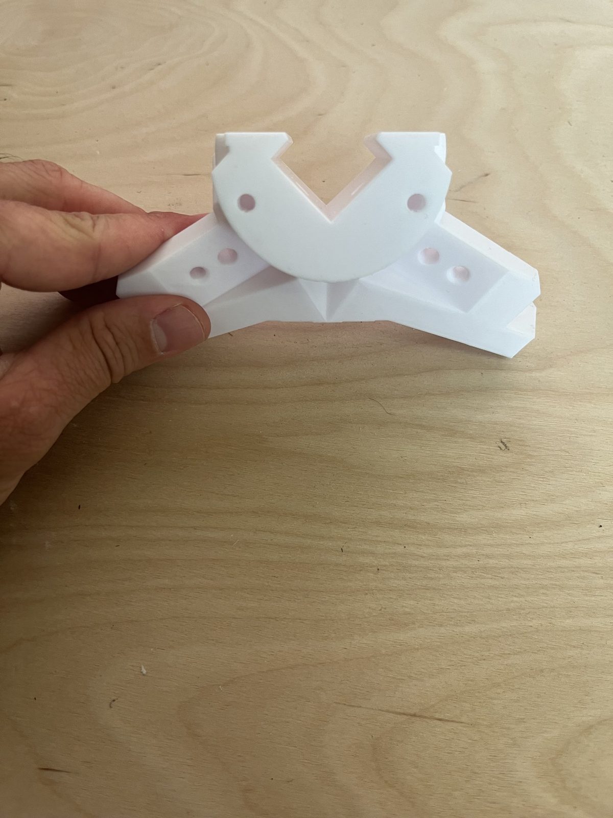
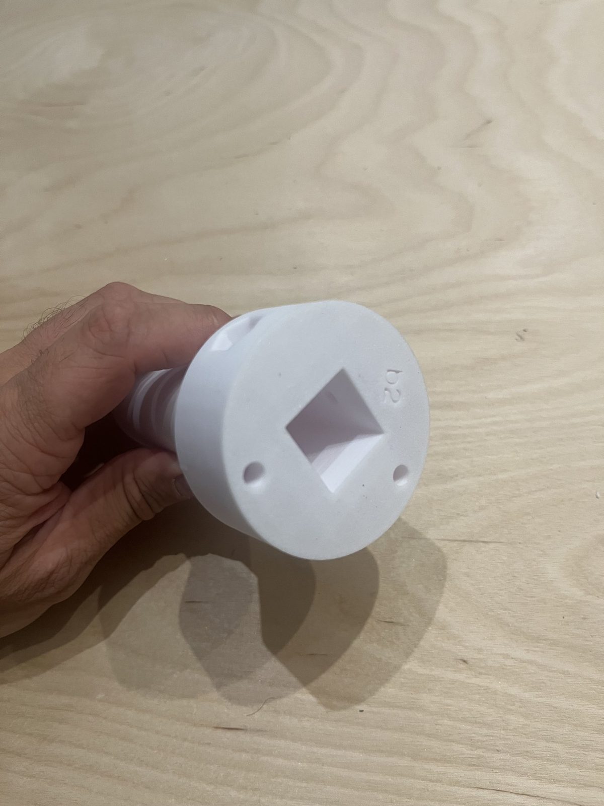
Step 1 Mount the bottom-vertical leg to the side bracket
Set the bottom-vertical leg's flanged top into the U-shaped opening of the side bracket, tube pointing down. Line up the screw holes shown above and drive two M5 × 16 mm socket head screws down through the flange into the side bracket.
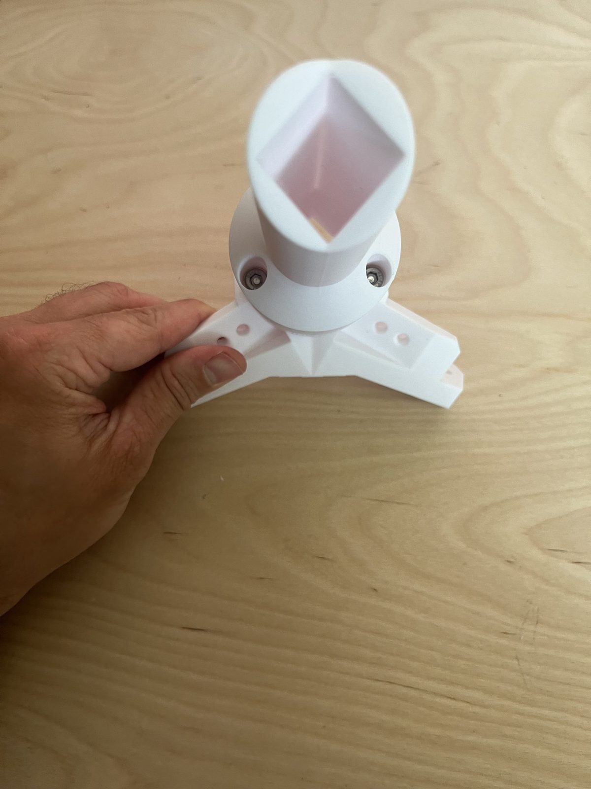
Drive these tight. As self-tapping screws into printed plastic, they hold best if seated firmly the first time, repeated removal and reinsertion strips the plastic threads.
Step 2 Insert the C-Layer vertical support
Slide the C-Layer vertical support (the vertical aluminum extrusion) down through the side bracket's U-shaped clamp and into the square socket in the bottom-vertical leg below. The socket is sized to the extrusion's profile, so it can only seat in the correct orientation.
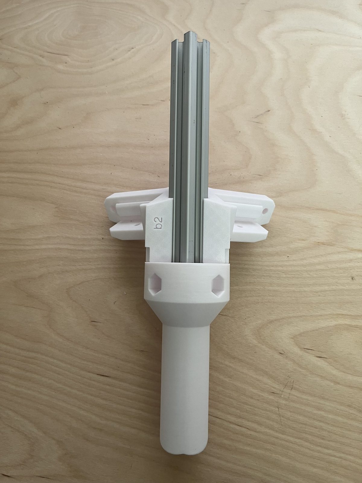
Step 3 Screw the bracket down onto the extrusion
Two more M5 × 16 mm screws clamp the side bracket against the C-Layer vertical support to hold it firmly in place.
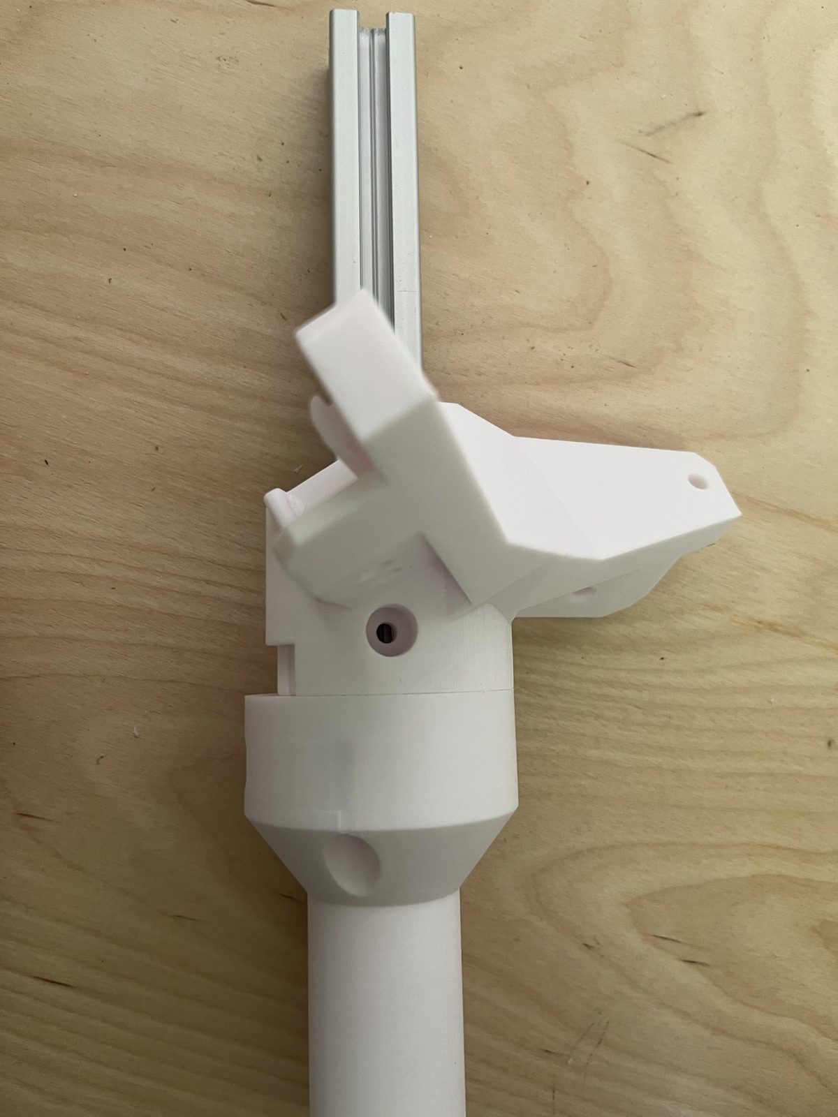
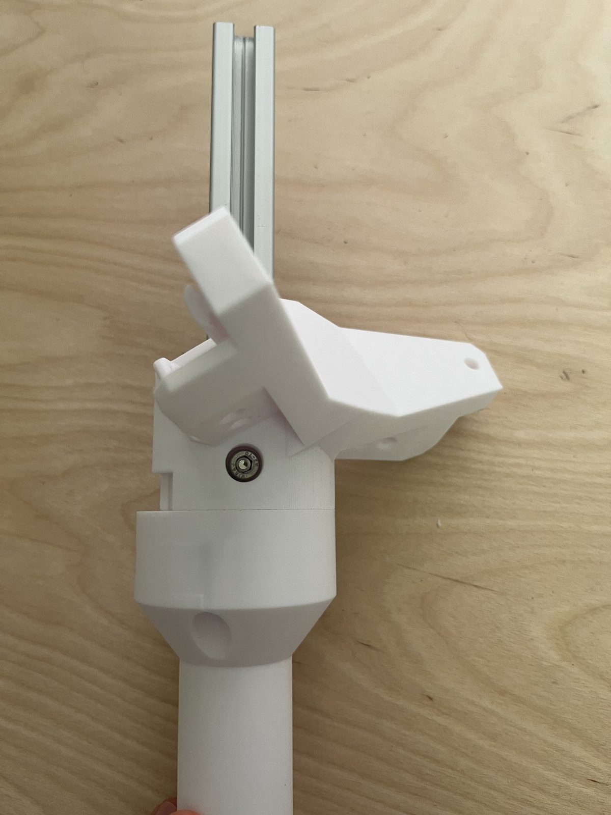
Step 4 Clip on the cover
Clip the cover onto the side bracket to close it off. The cover takes no screws, it's a snap fit.